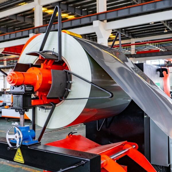
Optimize Laser Power and Cutting Speed for Material-Specific Precision
Properly balancing laser power and cutting speed is critical for achieving high-quality results with your fiber laser cutting machine. This optimization ensures clean cuts while minimizing energy waste and material distortion.
Selecting the Right Laser Power for Different Materials
When working with thin stuff like plastics or foils, it's best to keep the power down between 10W and 100W so they don't burn through. Stainless steel and aluminum tell a different story though, needing much stronger equipment ranging from 500W all the way up to 6,000W just to get proper results. Take cutting speed for instance. According to recent industry numbers from 2025, those big 40 kW laser machines slice through 20mm thick steel about six times quicker than smaller 15 kW versions. Material thickness isn't everything either. Copper and brass actually demand around 15 to 20 percent more power compared to regular steel because of how quickly they conduct heat away from the cutting area. Getting this right matters a lot for anyone serious about efficient manufacturing.
Adjusting Cutting Speed Based on Material Thickness and Type
The faster cutting speed tends to drop as materials get thicker. Take a standard 6 kW laser cutting machine for example it can handle 1 mm carbon steel at around 33 meters per minute, but when faced with 20 mm thick plates, the speed plummets to just 12 m/min. Working with reflective metals such as aluminum is even trickier. These materials need about 20 percent less speed compared to steel because they scatter the laser energy so much. The good news is newer systems with dynamic power controls are changing things. These advanced machines adjust their speed on the fly during operation, which cuts down overall processing time by roughly 18% when dealing with parts that have varying thicknesses across different sections.
Balancing Power and Speed to Reduce Kerf Width and Heat-Affected Zones
When too much power is applied during cutting operations, it actually makes the cut wider what we call kerf by as much as 25%. On the flip side, if the machine isn't moving fast enough, all that extra heat builds up and starts to warp those thin metal sheets. Take 3mm thick stainless steel for example. Running the laser at around 2500 watts while maintaining a feed rate of about 4 meters per minute gives us a nice tight cut width of approximately 0.15mm. That's roughly half again as narrow compared to what most people typically set their machines to. Getting this right matters because when done properly, it cuts down on those problematic heat affected areas by about 30%. And that means the metal stays stronger and maintains its original properties after cutting, which is exactly what manufacturers want to see.
Case Study: Enhancing Stainless Steel Cut Quality With Dynamic Power Control
A manufacturer reduced dross formation by 72% in 8 mm stainless steel by implementing sensor-driven power modulation. The system adjusts output every 0.8 seconds based on thermal feedback, maintaining optimal energy density across uneven surfaces. This approach improved edge squareness tolerance from ±0.2 mm to ±0.05 mm, meeting aerospace-grade specifications.
Choose and Control Assist Gas for Clean, Dross-Free Cuts
Matching assist gas type to material—oxygen for carbon steel, nitrogen for stainless
The best outcomes from fiber laser cutting happen when we match the right assist gas to the specific material being worked on. When dealing with carbon steel, oxygen works really well because of that heat-producing reaction it creates during cutting. This can boost cutting speed by around 30% for plates that are at least 6mm thick, although there will be some oxidation along the cut edges. Stainless steel tells a different story though. Nitrogen is the go-to choice here since it stops oxidation from happening altogether. The metal stays corrosion resistant too, which is important for many applications. Most industry guidelines suggest using nitrogen with purity above 99.995%, something manufacturers typically specify in their process parameters.
Optimizing gas pressure and flow rate to improve edge quality
Balancing gas parameters reduces dross while minimizing operational costs:
- Thin stainless (1–3 mm): 14–18 bar nitrogen pressure achieves burr-free cuts
-
Carbon steel (8–12 mm): 1.2–1.5 bar oxygen flow optimizes slag removal
Excessive pressure (>20 bar) creates turbulent gas flow, increasing kerf width by 15–20% in thin materials.
Comparative benefits of nitrogen vs. oxygen in fiber laser cutting machine applications
Using oxygen cuts down the processing time needed for structural steel parts, although there's usually some grinding required after cutting if the surface has paint on it. Stainless steel gets better results with nitrogen because it produces edges ready for welding right away without needing extra work afterward. The downside? Gas costs go way up too expensive really about forty to sixty percent more than what oxygen setups typically cost. Industry reports looking at how best to use these gases show something interesting though. Even though nitrogen is pricier, companies actually see around an 18 percent boost in return on investment when they cut those high quality finishes, which makes sense considering the money saved from not having all those extra steps later on.
Emerging trend: Smart gas delivery systems for real-time pressure adaptation
Advanced sensors now automatically adjust gas parameters during piercing and contouring phases. One automotive supplier reduced nitrogen waste by 22% while maintaining ±0.05 mm edge consistency across stainless exhaust components using adaptive flow control. These systems compensate for nozzle wear and material inconsistencies, critical for high-mix production environments.
Achieve Maximum Precision with Proper Focus and Beam Alignment
Setting focal length and lens selection for concentrated beam intensity
Material thickness dictates lens selection—5-inch lenses concentrate energy for thin sheets (<5 mm), while 7.5-inch variants spread heat evenly in 20 mm+ plates. A ±0.1 mm focal tolerance reduces kerf width variations by 12% (Industry Standard 2023). Key factors:
- Focal position shifts: +0.5 mm for reflective metals like aluminum
- Beam collimation: Reduces divergence to <1.2 mrad for stable energy density
- Anti-reflective coatings: Boost lens lifespan by 40% in high-power fiber laser cutting machine operations
Fine-tuning focus position to minimize taper and ensure square cuts
Dynamic Z-axis compensation counters thermal lensing effects during prolonged cuts. For 6 mm stainless steel, raising focus 0.2 mm above the surface reduces taper angle from 1.5° to 0.3°. A 2023 study showed auto-focus systems maintain ±0.05 mm positional accuracy across 8-hour production runs using laser triangulation feedback.
Calibrating laser beam alignment for consistent perpendicularity
Mirror alignment tolerance below 0.02° prevents beam walk-off, critical for multi-kilowatt fiber lasers. Weekly checks with alignment irises and beam profilers reduce angular deviation by 75% compared to monthly routines. Multi-axis calibration protocols correct:
Parameter | Target Value | Impact on Cut Quality |
---|---|---|
Beam centering | <0.1 mm variance | Eliminates 95% of edge striations |
Nozzle concentricity | 0.05 mm tolerance | Reduces gas turbulence by 40% |
Fixed vs. dynamic focus: Evaluating performance in high-speed operations
Dynamic focus heads outperformed fixed systems by 15% in cutting speed while maintaining edge squareness under 0.5° during 3D contouring tests (Laser Processing Consortium 2024). Hybrid systems now use pressure sensors and capacitive height tracking to adjust focus 300 times per second—critical when processing warped sheets.
Ensure Consistent Cut Quality Through Material Preparation and Maintenance
Preparing materials: Removing oils, oxides, and coatings before cutting
When there are contaminants such as lubricants, rust buildup, or zinc coatings present, they tend to interfere with how well the laser beam gets absorbed during cutting operations. This leads to problems like inconsistent cuts and lots of unwanted dross formation. Having a properly cleaned surface makes all the difference when it comes to getting that consistent energy transfer from the laser, which means less work needed after the initial cut. Take aluminum sheets for instance - those that have been stripped of oil show around 40% fewer issues with rough edges than what we typically see on surfaces that haven't received any treatment at all. The cleaning approach should match the specific material being worked with. Chemical solvents work best against oily residues while mechanical methods like sanding tackle tough oxide layers effectively. Just remember that different materials respond differently to various cleaning techniques so some trial and error might be necessary depending on the situation.
Implementing a standardized inspection checklist for incoming materials
Develop a 5-point verification process:
- Flatness tolerance: ≤ 0.5 mm/m² to prevent focal length variations
- Surface reflectivity: Measure with handheld spectrophotometers
- Coating thickness: Verify uniformity using ultrasonic gauges
- Alloy certification: Cross-check against material datasheets
- Storage conditions: Confirm dry storage to prevent condensation
Daily maintenance routines: Lens cleaning, nozzle checks, and chiller care
- Lens maintenance: Clean protective windows every 4 operational hours with lint-free wipes and optical-grade alcohol
- Nozzle alignment: Use alignment gauges to maintain 0.05 mm concentricity with the laser beam
- Chiller performance: Monitor coolant temperature (20°C ±1°C) and flow rate (2 L/min)
Preventative maintenance to sustain fiber laser cutting machine performance
Replace consumables on manufacturer-recommended intervals:
Component | Replacement Interval | Performance Impact |
---|---|---|
Focus lens | 150 cutting hours | Beam dispersion ≤ 5% |
Nozzle tips | 300 cutting hours | Gas flow consistency |
Beam delivery seals | Annually | Power loss prevention |
Scheduled recalibration of motion systems and beam path alignment maintains positioning accuracy within ±0.01 mm—critical for complex geometries in high-volume production.
Evaluate and Monitor Cut Quality Using Proven Metrics and Advanced Tools
Key Cut Quality Indicators: Dross, Striations, Taper, Burrs, and Edge Squareness
When it comes to judging how well a fiber laser cutting machine is performing, there are basically five key things technicians look at. First off, if the dross left behind after cutting measures less than 0.15 mm thick, that usually means the gas flow is balanced correctly. But when we see those weird stripe patterns along the cut edge, that often points to problems with either cutting speed or where the laser focus is set. Then there's edge squareness - most machines start having issues when deviations go beyond about half a degree, which typically means someone needs to adjust the nozzle position or check the beam path alignment. According to some research published by Fabrication Insights last year, nearly four out of five production holdups in manufacturing plants were actually caused by something pretty simple: workers not measuring taper angles properly in thick stainless steel sheets, where angles over 1.2 degrees cause all sorts of headaches down the line.
Metric | Ideal Threshold | Common Causes of Failure |
---|---|---|
Dross Height | ≤0.1 mm | Low assist gas pressure |
Edge Taper | ≤0.8° | Incorrect focal length |
Burr Width | ≤0.05 mm | Worn nozzle orifice |
Surface Roughness | Ra ≤3.2 μm | Unstable cutting speed |
Using Magnification and Surface Profilometry for Micro-Defect Detection
Operators achieve ≤5 μm measurement accuracy using 200X digital microscopes paired with contactless profilometers. This dual approach detects subtle irregularities like 10–15 μm micro-cracks in aerospace aluminum alloys that visual inspections miss. For high-reflectivity copper, polarized lens adapters reduce glare by 60% (Laser Systems Journal 2022), enabling precise heat-affected zone (HAZ) analysis.
Resolving the Speed vs. Precision Trade-off in Production Environments
Dynamic parameter algorithms reduce this conflict by 40%, per a 2023 International Journal of Advanced Manufacturing study. By correlating real-time sheet temperature sensors with adaptive power modulation, manufacturers maintain ±0.05 mm tolerance at 12 m/min cutting speeds—a 22% throughput gain versus static setups.
Future-Forward: AI-Powered Image Recognition for Real-Time Quality Monitoring
Vision systems with convolutional neural networks now achieve 99.1% defect classification accuracy across 47 material grades. The global market for AI-driven laser cutting analytics is projected to grow at 18.6% CAGR through 2030 (Market Research Future), with edge-computing modules enabling <50 ms anomaly detection without cloud latency.
FAQ
How do you determine the ideal laser power for cutting different materials?
The ideal laser power is determined by the material's thickness and thermal properties. Thin materials like plastics require lower power (10W to 100W), while metals like stainless steel and aluminum need higher power (500W to 6,000W).
Why is assist gas used during laser cutting, and how should it be selected?
Assist gas helps remove dross and improve edge quality. Oxygen is used for carbon steel to increase cutting speed, while nitrogen is preferred for stainless steel to prevent oxidation and maintain corrosion resistance.
What role does focal length play in laser cutting?
Focal length determines the concentration of the laser beam on the material. Shorter lenses are used for thinner sheets, while longer lenses spread heat over thicker plates. Proper focal length ensures consistent kerf width and cut quality.
Table of Contents
- Optimize Laser Power and Cutting Speed for Material-Specific Precision
-
Choose and Control Assist Gas for Clean, Dross-Free Cuts
- Matching assist gas type to material—oxygen for carbon steel, nitrogen for stainless
- Optimizing gas pressure and flow rate to improve edge quality
- Comparative benefits of nitrogen vs. oxygen in fiber laser cutting machine applications
- Emerging trend: Smart gas delivery systems for real-time pressure adaptation
- Achieve Maximum Precision with Proper Focus and Beam Alignment
- Ensure Consistent Cut Quality Through Material Preparation and Maintenance
-
Evaluate and Monitor Cut Quality Using Proven Metrics and Advanced Tools
- Key Cut Quality Indicators: Dross, Striations, Taper, Burrs, and Edge Squareness
- Using Magnification and Surface Profilometry for Micro-Defect Detection
- Resolving the Speed vs. Precision Trade-off in Production Environments
- Future-Forward: AI-Powered Image Recognition for Real-Time Quality Monitoring
- FAQ