 EN
EN


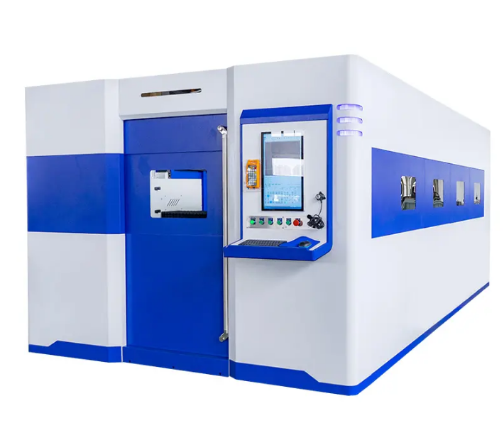
Why Alarm Codes Matter More Than the Laser Itself
A fiber laser cutting machine is only as productive as its uptime. Most operators can identify the moment something goes wrong, but translating that moment into a root cause diagnosis and a corrective action in under ten minutes separates shops that maintain high utilization from those that run through service calls for problems they could have handled themselves. Alarm codes are the machine's way of communicating failure mode information, and reading them accurately is a skill that pays dividends daily.
The following covers the most common alarm categories, what typically triggers them, and what a structured diagnostic response looks like.
Laser Source Alarms: Temperature, Power, and Communication Faults
Laser source alarms account for a significant share of fiber laser cutting machine downtime. The three most common subcategories are chiller temperature alarms, laser module communication faults, and power output deviation alarms.
Chiller temperature alarms typically appear when the cooling water inlet temperature exceeds the setpoint, often 20-22°C, or when the flow rate drops below the minimum threshold. Before calling for service, check whether the chiller's ambient temperature limit has been exceeded. A chiller rated for 40°C ambient in a summer environment that reaches 45°C will fault regardless of how well the machine is maintained. Cleaning the condenser fins and confirming the chiller enclosure isn't recirculating its own hot exhaust air resolves a significant percentage of these alarms without any parts replacement.
Laser module communication faults often trace back to loose fiber connectors rather than module failure. The optical fiber connecting the laser source to the cutting head is subject to vibration from the machine's motion system. Inspect the fiber connectors at both ends for seating and check for kinks in the fiber routing path.
Servo Drive Alarms: Overcurrent, Encoder Error, and Following Error
Servo drive alarms on the axis drives disrupt cutting cycles and, if left unaddressed, can cause tool path errors or machine positioning faults. The three alarm types that show up most frequently are:
1.Overcurrent alarms, which indicate the drive is drawing more current than its rated capacity. On X and Y axes, this often points to mechanical binding, contaminated linear guides, or a ballscrew that needs lubrication.
2.Encoder error alarms, which indicate a signal issue between the motor encoder and the drive. Check the encoder cable for damage at bending points, especially near cable carriers where flexing is repetitive.
3.Following error alarms, which trigger when actual axis position deviates from commanded position beyond a set tolerance. This can result from worn ballscrews, insufficient servo gain, or a mechanical load change from tooling or fixture mass that hasn't been accounted for in the servo parameters.
| Alarm Type | Most Common Root Cause | First Diagnostic Step |
|---|---|---|
| Chiller temperature high | Ambient overtemperature or condenser fouling | Clean condenser, check chiller placement |
| Laser communication fault | Loose fiber connector | Reseat fiber at source and head |
| Servo overcurrent | Guide contamination or ballscrew drag | Clean and lubricate linear guides |
| Encoder error | Cable damage at bend point | Inspect encoder cable routing |
| Following error | Ballscrew wear or servo gain | Run axis test cycle without cutting load |
| Nozzle height fault | Capacitive sensor contamination | Clean nozzle ceramic and sensor face |
| Gas pressure alarm | Regulator drift or supply issue | Check pressure at machine inlet regulator |
Capacitive Height Sensing Alarms and Nozzle Faults
The cutting head's capacitive height sensor maintains the focal distance between the nozzle and the material surface. Height sensing alarms are among the most operationally disruptive alarm types because they stop the cut mid-part, requiring a decision about whether to scrap or attempt a resume.
Nozzle height faults frequently stem from contamination on the ceramic ring that insulates the nozzle from the cutting head body. Even a thin film of oxidized spatter on the ceramic surface changes the capacitance reading and causes erratic height control. Removing and cleaning the ceramic with isopropyl alcohol, then reinstalling with the correct torque, resolves the majority of height sensing alarms that aren't related to actual sensor failure.
A job shop in Shandong running a 6 kW fiber laser on stainless steel was experiencing height fault alarms roughly every 40 minutes of production. Investigation found that the nozzle ceramic had developed micro-cracking from repeated thermal cycles, causing unpredictable capacitance values. Replacing the ceramic at the recommended service interval rather than running to failure eliminated the alarm pattern.
Gas Pressure and Purity Alarms
Assist gas pressure alarms signal that the machine is receiving gas at a pressure outside the programmed range. Before adjusting the machine's parameter set, verify the actual pressure at the inlet regulator rather than assuming the supply is stable. Nitrogen supply from a liquid dewar system shows pressure variation as the dewar level drops, and this variation can trigger alarms during the later portion of a cutting shift if the dewar isn't topped off in time.
Gas purity is less commonly monitored but affects cut quality on stainless and aluminum. Nitrogen purity below 99.95% for stainless steel cutting introduces oxidation on the cut edge that mimics the appearance of incorrect focus or power setting, leading operators to chase a machine problem that is actually a supply chain issue.
Control System and Communication Alarms
CNC and motion controller alarms related to communication timeouts or fieldbus errors often result from electrical noise rather than hardware failure. A servo drive with a failing filter capacitor can inject noise onto the communication bus that causes intermittent faults across multiple axes simultaneously. These faults tend to appear during high-speed positioning moves and disappear when the machine runs at reduced speed.
Shielded cable inspection and ground continuity verification are the appropriate starting points. If alarms persist after confirming cable integrity, measuring the DC bus voltage on the drive under load conditions can reveal whether a power supply component is degrading.
RAYMAX fiber laser cutting machines include alarm logging with time-stamped fault records, which helps maintenance personnel identify patterns in recurring alarms rather than treating each occurrence as an isolated event, a feature that becomes increasingly valuable as machines accumulate runtime hours.
Table of Contents
- Why Alarm Codes Matter More Than the Laser Itself
- Laser Source Alarms: Temperature, Power, and Communication Faults
- Servo Drive Alarms: Overcurrent, Encoder Error, and Following Error
- Capacitive Height Sensing Alarms and Nozzle Faults
- Gas Pressure and Purity Alarms
- Control System and Communication Alarms