

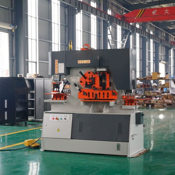
Understanding Bend Radius and Its Importance in Ironworker Operations
Bend Radius Definition and Importance in Metal Bending
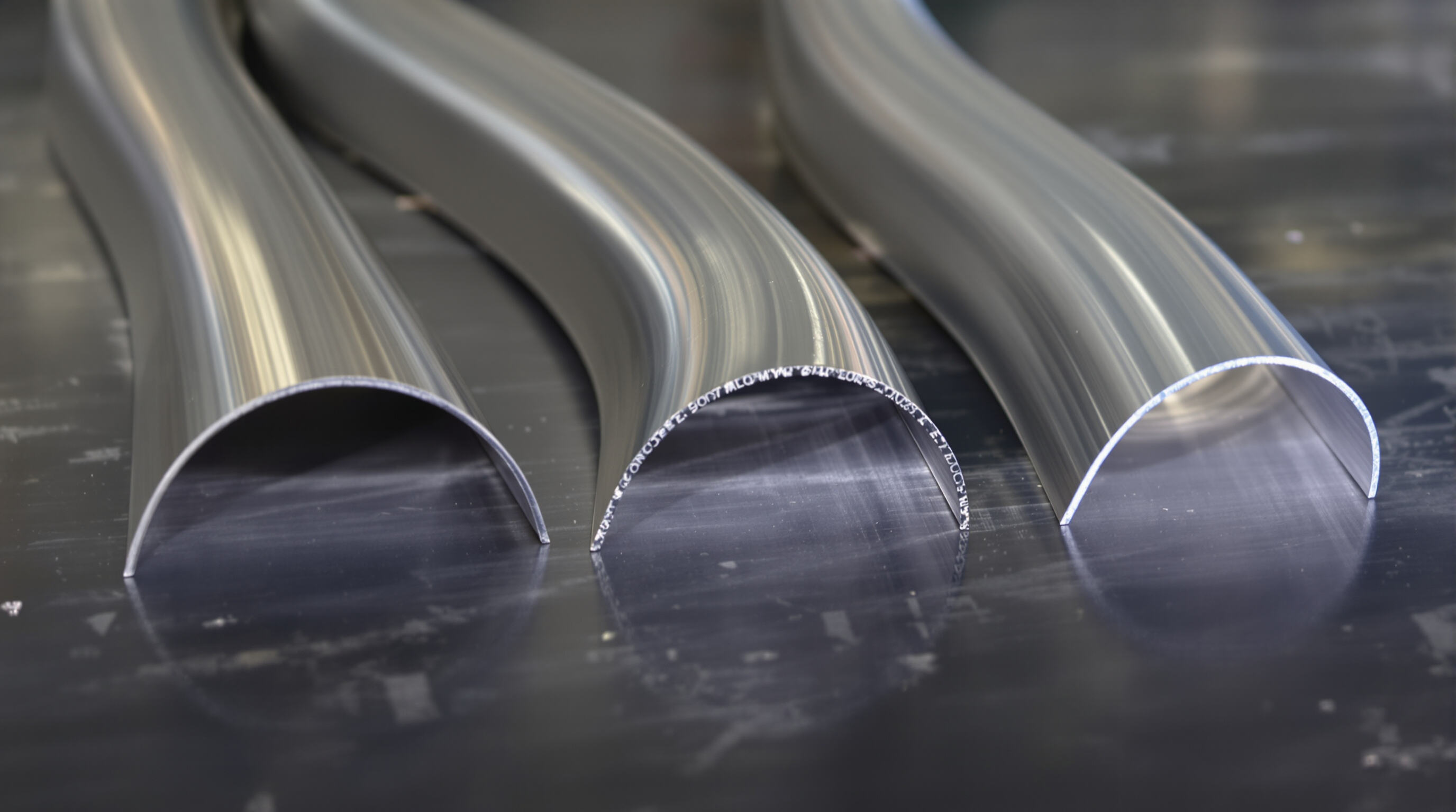
Bend radius refers basically to how curved a metal piece becomes when bent, measured from the centerline down to where the material starts curving inward. Getting this right matters a lot for several reasons. Components need proper structural strength, they must handle stress without breaking, and they should resist wearing out over time. When someone picks the wrong radius, bad things happen. If the curve is too tight, especially with high carbon steel, there's about a two thirds chance of cracks forming according to Fabrication Standards 2023. On the flip side, making the bend too wide weakens the part and makes it less efficient overall. The bottom line is that choosing the correct bend radius isn't just about following specs but actually affects whether parts will work properly once installed in real equipment.
The Relationship Between Bend Radius and Material Thickness
Material thickness (T) directly influences the optimal inner bend radius (Ir), commonly guided by the 1T Rule, where Ir equals T for ideal results. Deviations are necessary based on thickness:
- Thin materials (<6mm): Ir ∆ T minimizes springback and edge distortion
- Medium thickness (6–12mm): Ir = 1.25–1.5−T balances formability and tool wear
- Thick plates (>12mm): Ir = 2–3−T prevents die damage and ensures even strain distribution
Adhering to these guidelines supports consistent angular accuracy within ±0.5° in CNC-controlled operations.
Inner Bend Radius to Thickness Ratio (Ir/T) and Its Influence
The Ir/T ratio is a key metric in ironworker planning, influencing three critical outcomes:
- Springback magnitude: Ratios below 0.8 increase angular rebound by 15–22%
- Tool longevity: Maintaining Ir ∆¥ T extends die life by 40%
- Surface quality: Ratios under 1 amplify grain deformation, often requiring post-processing
Modern CNC press brakes achieve Ir/T precision within ±0.1T using real-time angle compensation, enabling reliable repeatability across mixed-material production runs.
Material Properties and Their Impact on Bend Radius Control
Material Type and Its Effect on Minimum and Optimal Bend Radius
The bend radius needed varies quite a bit between different materials because they just don't behave the same when bent. For instance, low carbon steel can handle pretty tight bends, usually around 0.8 to 1.5 times the material thickness. Stainless steel tells a different story though. We generally need bigger radii here, somewhere between 2 and 4 times thickness, otherwise there's a good chance of cracks forming during the process. Aluminum sits somewhere in the middle ground. Most aluminum alloys work well with radii ranging from about 1 to 3 times their thickness, but this does depend heavily on how tempered the particular alloy happens to be. Because these properties differ so much across materials, shops need specific bending procedures for each type if they want to maintain consistent results and product quality throughout production runs.
How Yield Strength and Ductility Influence Bend Radius Outcomes
When talking about bendability, two main factors come into play: yield strength and ductility. Materials with high yield strength such as 304 stainless steel, which has around 215 MPa, don't deform easily. Because of this property, they need much bigger minimum bend radii compared to mild steel at similar thickness levels. Mild steel actually has a yield strength of about 170 MPa but makes up for it with better ductility. For instance, mild steel can handle tighter bends when compared to aluminum. At 3mm thickness, mild steel offers roughly 40% elongation while aluminum only provides about 15%. This difference means manufacturers can achieve bend radii that are approximately 30% smaller with mild steel before cracks start forming during the bending process.
Case Study: Comparing Bend Radius Performance in Mild Steel vs. Stainless Steel
A controlled test on 3mm sheets illustrates material-specific challenges:
| Material | Thickness | Minimum Bend Radius | ir/t Ratio | Bend Success Rate |
|---|---|---|---|---|
| Mild Steel | 3mm | 2.4mm | 0.8 | 98% (no cracking) |
| 304 Stainless | 3mm | 6mm | 2.0 | 82% (edge cracks) |
This 150% increase in required radius for stainless steel underscores the importance of adjusting tooling and tolerances based on material behavior in production settings.
Tooling and Die Selection for Precision Bend Radius in Ironworker Operations
Die Opening Width and Its Impact on Bend Radius
The width of the die opening plays a major role in getting those bend radii right. According to studies cited in the latest Tooling Efficiency Report from 2024, when manufacturers go for die openings that are around 8 to 10 times thicker than the material itself, they see about a quarter improvement in how consistent those bends turn out compared to what happens with narrower or fixed width dies. Now, narrow dies do allow for tighter bends which can be great for certain projects, but there's always that nagging issue of deformation risks, especially noticeable when working with thicker metals or those high strength alloys everyone loves these days. On the flip side, going wider actually helps combat springback problems. This matters quite a bit when dealing with stainless steel workpieces or any other materials known for their tendency to spring back after forming.
Types of Dies Used in Bending Operations
Three main die types support modern ironworker workflows:
- V-dies: Most common, used in approximately 68% of sheet metal bending applications for standard 90° bends
- Rotary bending dies: Reduce surface friction by 40%, ideal for coated or polished finishes
- Air bending dies: Allow adjustable angles through controlled punch depth, supporting flexible production runs
Role of Tooling and Die Selection in Bending Accuracy
Using high-grade tool steel reduces wear by 50% compared to standard alternatives (2023 Material Durability Study). Operators following proper tool steel selection practices achieve ±0.1mm radius tolerances even in 0.5"-thick plates. Heat-treated dies maintain dimensional stability over 10,000+ cycles, making them essential for high-precision industries like aerospace and automotive manufacturing.
Industry Paradox: Standard Die Widths vs. Precision Radius Control
Even with all the improvements we've seen in CAD/CAM technology, around 60 percent of metal fabrication shops still stick with those 12mm dies no matter what thickness material they're working with. This practice leads to about 18% waste when dealing with stainless steel according to the latest Fabrication Waste Analysis from 2024. The smarter shops out there are starting to switch to adjustable die systems instead. These newer setups can change the V-opening width as needed based on actual material thickness measurements taken during production. What does this mean for shop owners? Better radius control across different materials and noticeably higher yields at the end of the day.
Bending Processes and Machine Capabilities in Radius Control
Effects of Different Bending Processes (Air Bending, Bottoming, Coining)
Ironworkers employ three primary bending methods, each affecting radius control differently:
- Air bending: Uses three-point contact with minimal tool contact, offering flexibility but requiring overbending to compensate for springback
- Bottoming: Compresses material fully into the die for higher angular accuracy
- Coining: Applies extreme pressure to permanently deform the material, eliminating springback and enabling ±0.1 mm radius consistency
Air bending typically requires 15–20% larger radii than coining due to inherent springback effects.
Springback Compensation Techniques in Air Bending
Springback remains a major challenge in air bending, causing radius deviations of up to 12% in mild steel (Srinivasan et al., Int. J. Mater. Eng. Innov. 2013). Effective countermeasures include:
- Overbending by 2°–5° to offset expected rebound
- Incremental bending with CNC-controlled corrections
- Utilizing real-time feedback systems to dynamically adjust punch depth during operation
Process Comparison: Radius Consistency in Coining vs. Air Bending
While coining delivers superior precision (±0.1 mm radius consistency), it demands three times the tonnage of air bending and increases tooling costs. Air bending offers faster cycle times and lower energy use but exhibits ±0.5 mm variance without active compensation—highlighting a tradeoff between precision and operational efficiency.
Press Brake Machine Functionality and Precision Bending
Modern press brakes integrate hydraulic systems for thick materials and electric servo-drives for thin-gauge work, achieving angular tolerances of ±0.25°. This hybrid functionality supports precise radius control across diverse production requirements.
Strategy: Integrating CNC Controls for Repeatable Bend Radius Outcomes
CNC integration reduces bend radius variability by 60% through automated adjustments for material hardness, optimized toolpaths for multi-axis setups, and closed-loop monitoring of punch deflection. This level of control enables ±0.15 mm repeatability across batches, meeting stringent specifications in aerospace and medical device manufacturing.
Calculations and Measurement Techniques for Bend Radius Accuracy
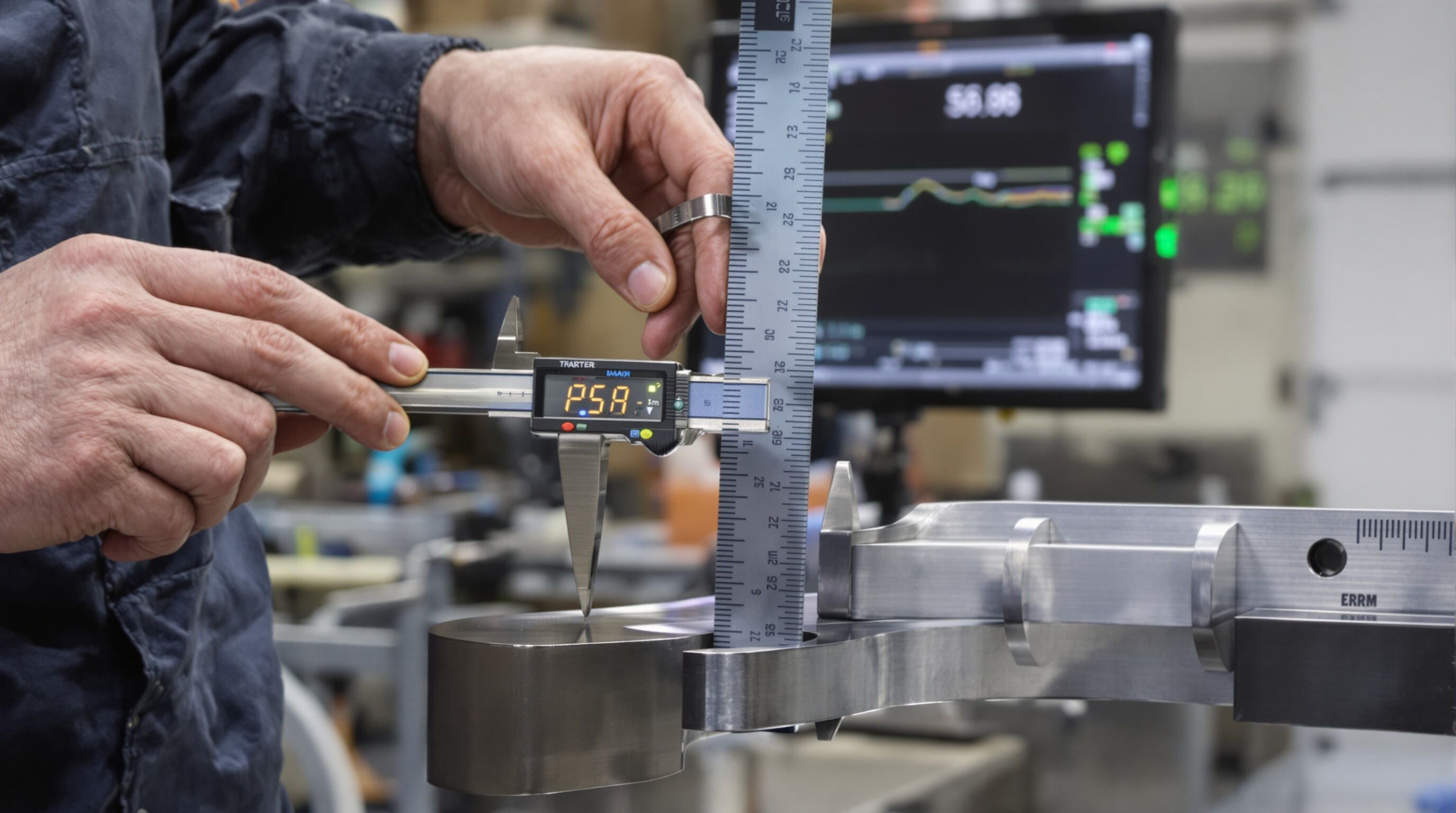
Bend Allowance (BA) Calculation and Application
Getting good control over bend radii really begins with figuring out what's called the bend allowance or BA for short. This basically measures how much material gets used up when something bends. There's this formula people use: BA equals angle multiplied by pi divided by 180 times inner radius plus K factor times thickness. The formula takes into account several factors including the actual bend angle itself, the inside radius dimension, how thick the material is, and that mysterious K factor which has to do with where the neutral axis shifts during bending. According to some research published last year in the fabrication field, shops that actually calculate their bend allowances instead of just guessing around save between roughly 18% to maybe even 22% on wasted materials compared to those old fashioned trial and error methods.
Bend Deduction and Flat Pattern Length Determination
Bend deduction (BD) accounts for the difference between total flange lengths and the developed flat pattern. Advanced ironworker software calculates BD using key variables:
| Factor | Influence on BD |
|---|---|
| Material Type | ±3-8% variance in values |
| Bend Angle | Direct proportional link |
| Tooling Profile | 12-15% adjustment range |
This data-driven method achieves ±0.25mm accuracy in flat pattern development across 2–12mm steel plates.
Data Point: Formula-Based Prediction of Bend Radius Using ir/t Ratios
Knowing the ir/t ratio helps figure out how tight a metal can be bent before it cracks. Most shops find that mild steel works well with about a 1 to 1 ratio, but stainless needs something closer to 2 to 1 if they want to avoid those pesky stress fractures. Some factories have tested this stuff and found that when workers combine these formulas with actual measurements taken while the metal is being worked on, their results come pretty close most of the time. One plant reported getting around 95% accurate bends in their automated systems, which isn't bad considering all the variables involved in metalworking.
Frequently Asked Questions
What is bend radius?
Bend radius is how curved a metal piece becomes when bent, measured from the centerline down to where the material begins to curve inward.
Why is material thickness important in determining bend radius?
Material thickness affects the optimal inner bend radius, commonly guided by the 1T Rule, helping balance formability and tool wear.
How do material properties affect bend radius?
The required bend radius varies between materials due to differences in yield strength and ductility, impacting their behavior when bent.
How does tooling affect bend radius precision?
Tooling, especially die selection and opening width, plays a crucial role in achieving precise bend radii and mitigating issues like springback.
What techniques help in compensating for springback?
Techniques such as overbending, incremental bending with CNC-controlled corrections, and real-time feedback systems can offset springback effects.
Table of Contents
- Understanding Bend Radius and Its Importance in Ironworker Operations
- Material Properties and Their Impact on Bend Radius Control
- Tooling and Die Selection for Precision Bend Radius in Ironworker Operations
-
Bending Processes and Machine Capabilities in Radius Control
- Effects of Different Bending Processes (Air Bending, Bottoming, Coining)
- Springback Compensation Techniques in Air Bending
- Process Comparison: Radius Consistency in Coining vs. Air Bending
- Press Brake Machine Functionality and Precision Bending
- Strategy: Integrating CNC Controls for Repeatable Bend Radius Outcomes
- Calculations and Measurement Techniques for Bend Radius Accuracy
- Frequently Asked Questions