 EN
EN


The Structural Logic That Sets Guillotine Machines Apart
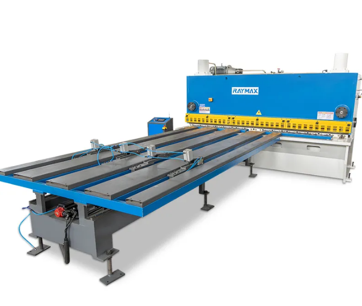
When the cutting task involves thick plate, high-tensile steel, or long cut lengths at sustained production volumes, the guillotine shearing machine tends to outperform swing beam alternatives by a margin that becomes hard to ignore. The difference isn't primarily about blade travel distance or motor size. It comes down to how each design handles the force vector during the cutting cycle.
In a swing beam design, the upper blade follows an arc. The cutting angle changes slightly throughout the stroke, which limits how aggressively the rake angle can be set without introducing sheet distortion. A guillotine design keeps the upper blade on a true vertical or near-vertical linear path throughout the stroke. That geometric consistency allows steeper rake angles on thicker material without the blade catching or the sheet walking, which is why guillotine configurations dominate in applications where plate thickness regularly exceeds 10 mm.
Frame Rigidity and Blade Deflection Under Load
One of the more underappreciated aspects of guillotine shear performance is frame behavior under load. At high tonnage, a frame that allows even fractional millimeter deflection will produce tapered cuts, where the blade angle shifts as the frame flexes. Premium guillotine shears use box-section welded steel frames with internal ribbing, and the blade beam itself is designed with sufficient section modulus to resist bending across its full length.
A fabrication shop handling 16 mm structural steel plate for heavy equipment manufacture in northeastern China ran a side-by-side evaluation of their existing swing beam machine against a guillotine unit of equivalent rated tonnage. The guillotine produced consistent cut squareness within 0.3 mm per 1000 mm of cut length, compared to 0.7 mm variation on the swing beam, specifically on 12 mm and above plate. The difference was attributed primarily to blade beam rigidity under load rather than any parameter difference in setup.
Blade Replacement Intervals and Wear Characteristics on Hard Material
Guillotine blades on heavy plate work wear differently than blades used for thin gauge sheet. The full-face blade contact on guillotine designs distributes wear more evenly across the blade face than the progressive contact pattern in swing beam machines. This matters because blade indexing and replacement frequency directly affects per-cut tooling cost.
| Material Type | Typical Thickness Range | Expected Blade Life (Cuts) | Recommended Blade Grade |
|---|---|---|---|
| Mild steel (A36/S235) | 6-16 mm | 80,000-120,000 | Cr12MoV or equivalent |
| High-strength steel (S355/A572-50) | 6-12 mm | 45,000-70,000 | H13 tool steel |
| Stainless steel (304/316) | 3-10 mm | 30,000-55,000 | H13 or D2 tool steel |
| Aluminum alloy | Up to 20 mm | 150,000+ | Cr12 or 6CrW2Si |
Blade clearance management is more critical on hard materials because the penalty for running with excessive clearance shows up as pronounced rollover and secondary fracture on the cut face, which can complicate downstream welding fit-up.
Hydraulic System Sizing and Pressure Management
A guillotine shear's cutting capacity is directly tied to its hydraulic system. The cylinder bore size, operating pressure rating, and pump flow rate together determine how the machine handles sudden resistance increases, such as when cutting plate with surface scale or variable cross-section.
Operating pressure on production-grade guillotine shears typically runs between 18 and 25 MPa. Systems that allow pressure adjustment per job are more practical in mixed-material shops than fixed-pressure configurations, because running at maximum system pressure for thin gauge material accelerates seal wear without providing any process benefit. According to hydraulic component manufacturer Parker Hannifin's application notes, seal life in hydraulic cylinders under cyclic load is inversely related to peak pressure excursions, meaning pressure management discipline directly extends service intervals.
Cut Length Capacity and Back Gauge Precision
Guillotine shears are available in cut length capacities from 1000 mm up to 6000 mm on production models, with the back gauge providing the primary method for controlling cut width. Back gauge precision on modern CNC guillotine shears is typically specified in the range of plus or minus 0.1 mm repeatability, which is sufficient for most structural and general fabrication applications.
For applications requiring tighter positional control, servo-driven back gauges with encoder feedback offer repeatability closer to plus or minus 0.05 mm. The practical value of this precision depends on what happens downstream of the shear. If cut blanks go directly to a CNC press brake, the back gauge tolerance feeds directly into the bend position accuracy of the formed part.
Matching Machine Capacity to Production Demands
Choosing a guillotine shear by maximum rated tonnage alone is a common procurement mistake. Rated tonnage at maximum thickness is only useful if the machine will regularly cut at that thickness. For shops with a material mix spanning 4 mm through 16 mm, a machine rated for 16 mm at maximum tonnage will spend most of its working life well within its comfort zone, which is actually positive for frame fatigue life and hydraulic system longevity.
RAYMAX guillotine shearing machines are built with this operational range in mind, covering configurations from moderate plate to heavy structural work, with hydraulic systems and blade beam designs that reflect the real loading conditions of production environments rather than peak-only specifications.
Table of Contents
- The Structural Logic That Sets Guillotine Machines Apart
- Frame Rigidity and Blade Deflection Under Load
- Blade Replacement Intervals and Wear Characteristics on Hard Material
- Hydraulic System Sizing and Pressure Management
- Cut Length Capacity and Back Gauge Precision
- Matching Machine Capacity to Production Demands