

Understanding Hydraulic Pressure in Press Brake Operation
Working Principle of Hydraulic Press Brakes and System Components
Hydraulic press brakes operate on Pascalâs Law, using incompressible fluid to transmit and amplify force. The system consists of three core components:
- Hydraulic pump: Generates flow to build pressure
- Control valves: Direct oil to actuators and regulate pressure thresholds
- Cylinders: Convert hydraulic energy into linear motion for ram displacement
This closed-loop design enables force multiplication exceeding 1:100, allowing precise bending of thick metals (â¥10mm) with minimal operator effort.
Role of Electro-Hydraulic Servo Systems in Precision Bending
Modern press brakes use electro-hydraulic servo systems that adjust pump output in real time via CNC signals. Unlike constant-speed pumpsâwhich waste 30â40% energy (PrimaPress 2024 analysis)âservo-driven systems:
- Match flow to demand, reducing power consumption
- Achieve ±0.01mm positional accuracy through closed-loop feedback
- Respond to pressure changes within 0.5 seconds
These systems maintain bending forces up to 3,000kN while minimizing heat generation and improving energy efficiency.
Key Machine Parameters Affecting Bending Pressure and Performance
| Parameter | Impact on Bending Pressure | Optimal Range |
|---|---|---|
| Pump displacement | Determines maximum system pressure | 10â200 cm³/rev |
| Relief valve setting | Limits peak pressure to prevent overload | 70â700 bar |
| Ram speed | Influences dwell time and force consistency | 2â15 mm/s |
| Oil viscosity | Affects pressure transmission efficiency | ISO VG 32â68 |
Balancing these parameters ensures less than 1% force variation across the ram, critical when forming hardened steels or complex parts.
Core Components Governing Hydraulic Pressure Control
Valves, Pumps, and Cylinders: Functions in Pressure Regulation
Getting proper hydraulic pressure control means all the components need to work together smoothly. The pump takes mechanical energy and turns it into hydraulic power, while those directional valves and pressure regulators handle the flow rate and keep things from getting too intense. When it comes to actuators, they basically take the pressurized fluid and turn that into actual movement along a straight line. Take proportional valves as an example these days. They adjust how much fluid flows depending on what stage of the bending process we're at, which makes everything move nicer instead of jerking around. Problems happen when parts start failing though. Worn out pump seals or valves that stick can really mess up the whole system, making pressure unstable and causing those bends to come out wrong every time.
Force Uniformity and Hydraulic Control Mechanisms
Uniform force distribution across the ram is achieved through synchronized hydraulic subsystems. Electro-hydraulic servo systems use pressure transducers and closed-loop feedback to maintain ±1% force consistency during bending. This precision reduces springback variability in materials like stainless steel and aluminum. Key mechanisms include:
- Pressure-compensated pumps adapting to real-time demand
- Synchronization valves ensuring even cylinder actuation
- Accumulators stabilizing pressure during rapid direction changes
Without these, inconsistent bends and rework become common.
How Setup and Parameter Adjustments Influence Pressure Output
Initial setup determines system performance. Relief valve settings, pump displacement, and cylinder preload define the pressure ceiling. For example:
- Increasing relief valve pressure by 10% can raise bending force by 8â12%
- Over-tightened preloads increase seal friction, reducing effective force by 3â5%
- Contaminated filters or degraded oil can cause pressure drops over 15%
Operators should cross-check control panel readings with mechanical gauges during calibration to correct for sensor drift or hydraulic lag. Proper tuning ensures full rated tonnage delivery while protecting components from premature wear.
Step-by-Step Guide to Adjusting Hydraulic Bending Pressure
Preparing the Press Brake for Safe Pressure Adjustment
Power down the machine and apply lockout/tagout procedures. Inspect the ram, tooling, and hydraulic connections for damage. Clean die surfaces to ensure consistent force transmission. Confirm hydraulic oil levels meet manufacturer specificationsâlow fluid causes cavitation and pressure instability.
Calibrating Bending Pressure Using the Control Panel and Settings
To get started, head over to either the CNC interface or the manual control panel where material properties need to be entered. Things like thickness measurements and tensile strength values are important here. For instance, when working with 50 ksi steel compared to 35 ksi grades, expect around 20% higher pressure requirements. Next step involves setting the target pressure level. Most operators prefer using those handy pre-programmed profiles, but manual calculations work too if needed. And for anyone operating servo-hydraulic equipment specifically, don't forget to switch on the pressure feedback mode. This feature lets the system automatically adjust pump settings according to what the load demands during operation.
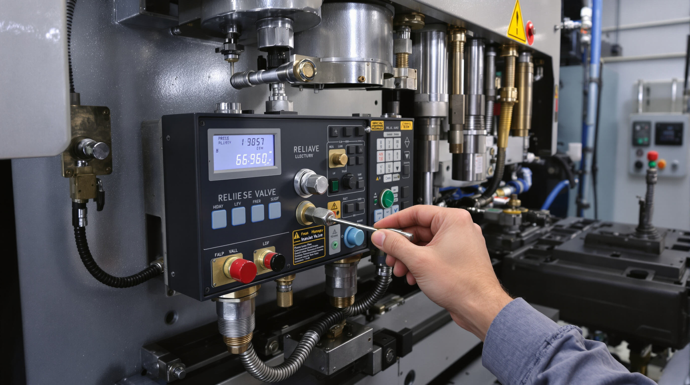
Adjusting Relief Valves and Pressure Regulators for Optimal Output
Locate the main relief valve at the pump discharge. Using a hex key, make incremental 5â10 psi adjustments while monitoring the system gauge. Turn clockwise to increase pressure, counterclockwise to reduce it. In dual-pump systems, balance circuit pressures to within 3% using a calibrated digital manometer.
Tuning Working Speed via Valve Adjustment
Adjust flow control valves to regulate ram speedâcritical for consistent bending. For ¼" steel, reduce descent speed by 15â20% compared to aluminum to accommodate greater springback. Validate speed-pressure coordination by testing 90° and 135° bends on scrap material.
Verifying Pressure Settings Using System Indicators and Gauges
After adjustments, perform three air bends on test coupons matching production material. Measure angles with a precision protractor (±0.1° tolerance) and monitor pressure across stroke positions. In servo-hydraulic systems, verify pressure remains within ±2% of setpoints throughout the full cycle.
Testing and Validating Pressure Adjustments for Accuracy
Performing Test Bends to Confirm Pressure Consistency
Start by doing some test bends on scrap material that has the same thickness and alloy composition as what will be used for actual production pieces. Keep an eye on how stable the pressure remains during these tests by checking the system's pressure gauges regularly. Compare what we see against our standard calibration benchmarks to spot any discrepancies early on. It makes sense to run tests at around 25%, halfway at 50%, and full capacity at 100% of the desired pressure level since this can reveal problems such as worn pumps or valves that respond too slowly. When there are noticeable differences from expected readings, make sure to record them properly following ISO 17025 guidelines so everything stays within acceptable industry tolerances, typically plus or minus about 1.5%.
Evaluating Bend Quality and Force Uniformity After Adjustment
Check bend angle consistency along the full ram length using precision angle finders. Springback differences exceeding 0.5° suggest uneven pressure from misconfigured proportional valves or synchronization errors. Confirm force uniformity by executing three consecutive bends under identical settingsâpressure fluctuations over 3% indicate the need for hydraulic circuit inspection.
Fine-Tuning Pressure Based on Real-Time Bending Feedback
Use the CNC interface to make micro-adjustments (5â10 bar increments) while observing strain gauge feedback. Advanced systems can refine pressure during production runs, compensating for variations in material hardness. Save optimized settings in machine memory; this reduces setup time for repeat jobs by 18â22%, according to 2023 fabrication efficiency studies.
Troubleshooting Common Hydraulic Pressure Issues
Diagnosing Causes of Inconsistent Bends in Hydraulic Press Brakes
When we see inconsistent bends happening, most times it's because the hydraulic pressure just isn't stable enough. There are several things that usually cause this kind of problem. The tools might be getting worn out after all these years, or maybe the dies aren't properly aligned anymore. Sometimes the calibration gets off track too. Believe it or not, something as small as a 0.1 mm offset in the die can really mess things up, cutting accuracy down by almost half in those fancy high precision servo systems. If someone wants to figure out what's going wrong, they should start by looking at whether the ram is parallel using those laser alignment gadgets, while also keeping an eye on the tooling for any signs of uneven wear spots. According to some studies floating around the industry, more than two thirds of these wild bend issues actually come down to problems with how thick or thin the fluid is becoming. Temperature fluctuations throughout the day or old degraded oil tends to change the viscosity, which throws everything off balance.
Resolving No-Pressure Faults: Pumps, Valves, and Blockages
No-pressure conditions typically arise from:
- Pump failures: Verify displacement volume against specifications
- Valve malfunctions: Test proportional valve solenoids for responsiveness
- Flow restrictions: Inspect suction lines for collapsed hoses, especially in cold environments (<50°F)
Before replacing components, cycle the system from 0â100% pressure three times to clear potential airlocks.
Identifying Hydraulic Leaks and System Integrity Issues
Internal leaks often appear as:
- Ram drift exceeding 0.5 mm/min (indicative of seal failure)
- Longer cycle times despite consistent tonnage
- Fluid temperatures above 140°F
Use infrared thermography to detect overheating valves or cylindersâa 15°F difference between adjacent components may reveal leakage paths. For critical joints, employ ultrasonic detectors capable of identifying leaks as small as 0.1 GPM.
FAQ
What is the working principle of hydraulic press brakes?
Hydraulic press brakes operate on Pascal's Law, using incompressible fluid to transmit and amplify force. They consist of key components such as a hydraulic pump, control valves, and cylinders for effective operation.
How do electro-hydraulic servo systems enhance precision bending?
Electro-hydraulic servo systems adjust pump output in real-time via CNC signals, reducing power consumption and achieving high positional accuracy through closed-loop feedback.
What factors influence bending pressure in hydraulic press brakes?
Key parameters affecting bending pressure include pump displacement, relief valve settings, ram speed, and oil viscosity. Proper tuning of these factors ensures force uniformity and performance.
How can I troubleshoot hydraulic pressure issues?
Common issues such as inconsistent bends may arise from unstable hydraulic pressure. Checking for worn tools, misaligned dies, or calibration drift can help resolve these problems.